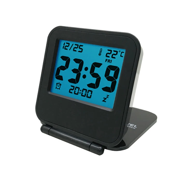

Connections to the LCD display unit are made through the 14 pins on the board.

The task of writing to the LCD becomes therefore a strict regime of following the manufacturer s directions. are all handled by the memory and microcontrollers provided. The tasks of refreshing the LCD screen, temporary storing display information, character information, etc.
Digital alarm clock mini project Pc#
Ground Figure 2: PC Speaker ConnectionĤ LCD Display: The LCD display unit comes with a multitude of support circuitry on-board. For this project, the Signal Source GND part of the speaker jack is wirewrapped with regular wire and connected to ground, while the tip of the speaker jack is connected to the signal source. The built-in amplifier simplifies any project by avoiding extra amplifier circuitry, especially when connection with the speakers is a snap. KEYPAD -User Input Key press FPGA -Debounce keypad input -Generate clock signal -Alarm Signal Speaker -Amplifies alarm signal into audible signal -0.5 sec clock pulse -debounced keypress data -Alarm On/Off Figure 1: Basic component structure HC11 -Stores time -Execute alarm clock algorithm -Drive LCD -Display Data -LCD Control LCD Display -Display time and instructions New Hardware PC Speakers: The PC speaker set inside the Microprocessor lab includes a built in amplifier ideal for amplifying small amplitude signals, such as one generated by the FPGA in thisproject.

These advantages include having keypad input instead of the single-button up-counting input for commercial alarm clocks, and using an LCD screen for a sleeker display.ģ The tasks performed by the individual components and the data they transmit are shown in Fig. The LCD display digital alarm clock provides several advantages over regular alarm clocks. These features make the HC11 the single necessary component to drive the LCD display. Furthermore, the LCD display has on-board display memory and built-in character display functions (cursor position, pre-programmed characters, etc.). The LCD screen s ability to display multiple characters allows for a friendlier menu-type display, replacing the various primitive methods of entering data into alarm clocks. In addition to being a suggested component for a final project, the LCD screen is a great component for the purposes of displaying numbers and characters. In short, both components are important counterparts of each other for the alarm clock. The FPGA also handles the debouncing of the keypad input since the procedure is best handled by permanent logic. This fact makes the FPGA an ideal choice for generating accurate timing signals. The FPGA board uses an external oscillator that generates accurate clock speeds. The HC11 s memory capabilities is used to store and increment time information, while its capability to perform more complex sequential tasks streams the functions such as changing into an editing mode for time editing, etc. The final project requirements are met by the tasks required of both components. The audible alarm will simply be a square wave signal generated by the FPGA amplified by a set of external computer speakers.Ģ Introduction The motivations behind the choice of the alarm clock as a final project are the following: its utilization of both the FPGA and the HC11, its use of an LCD display, and, finally, its advantages over a conventional digital alarm clock.

The FPGA and the on board clock oscillator will generate accurate timing signals and debounce keypad inputs, while the HC11 will store the time value, handle alarm clock functions, and generate the control signals to the LCD. Such a clock is constructed by combining the E157 FPGA board with the HC11 to control and generate the keypad inputs and LCD display outputs. With the availability of a twelve key keypad and LCD screen, a simple alarm clock can look much sharper, and work much better.
Digital alarm clock mini project code#


 0 kommentar(er)
